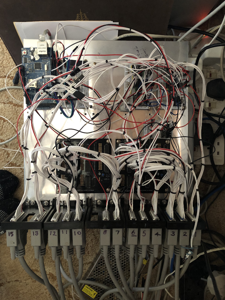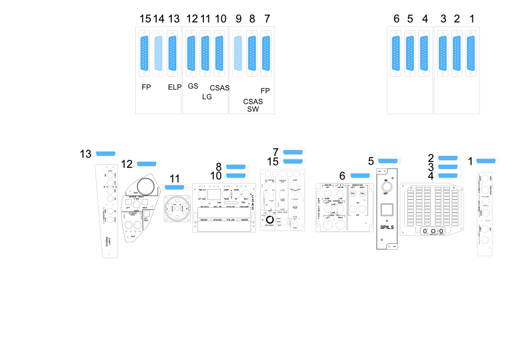
This is what the electronics controller looks like for about eleven
instruments/panels. Bear in mind that the Central Warning Panel has fifty plus LED's and the CSAS panel has sixteen which takes up at large chunk of this.
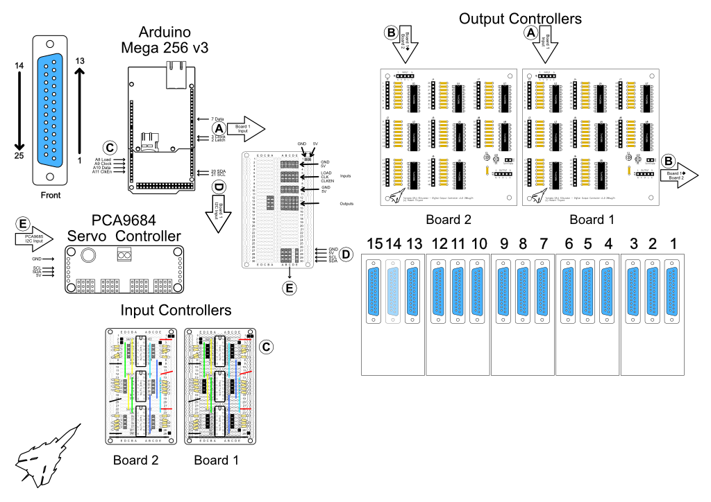
In the top left in an Arduino Mega with an ethernet HAT. Next to it on the
right is a small distribution board and far right are two input controllers.
At the bottom are two PCB's I designed that are chainable 48 channel output
controllers that the Arduino can switch on or off a 5 volt supply.
The two input controllers will shortly be replaced by PCB's that I have designed and made as the current system in a bit delicate. I made a mistake in the design of the input controller PCB's in that I missed off the mounting holes and I meant to provide some +5v connection that I actually connected to ground in error
To cover all of the future instruments
there will need be many more of these controllers.
Once perfected, I will include all of the plans for the electronics and the PCB's so that you can make them yourself (should you wish to).
I am tempted to use an ESP32 and a small ethernet board for the next one.
I could half the size of this then. This image is slightly old as it doesn't
show the servo controller that controls the needles on the Combined Surfaces Gauge.