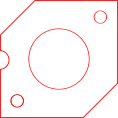
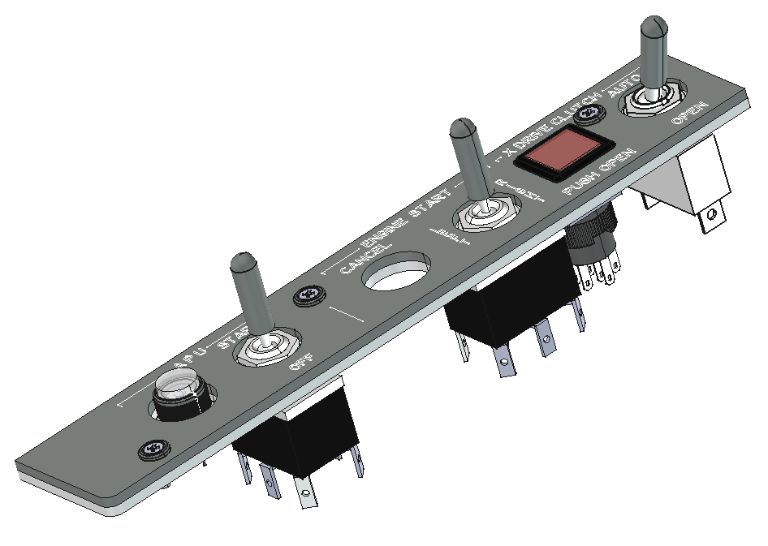
The Engine Start Panel is quite complex. I don't know what the cancel indicator/button looks like so I haven't been able to model this. At somepoint in the future I will be able to measure one and see how it works and make a 3D printed version.
 |
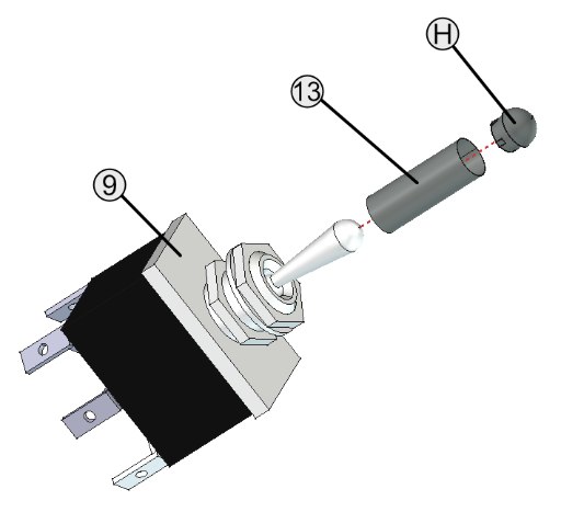 |
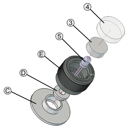
| Type B Indicator | 20x7mm Switch extenson tube |
 |
|
| 16mm Red Push Button |
The top and middle layers are 3mm opaque white acrylic. The run indicator lens is a yellow transparent 3mm acrylic and the lens 3mm clear acrylic.
| 1 | Laser cut the top layer in a laser cutter using white 3 mm white opaque acrylic sheet. |
| 2 | Laser cut the middle layer in a laser cutter using 3 mm white opaque acrylic sheet. |
| 3 | Laser cut part 12 in 3mm clear acrylic sheet. This gets glued under the middle layer as a base for the "RUN" indicator. |
| 4 | Paint the top layer grey. |
| 5 | Leave the protective film on the top and bottom of the middle layer and paint grey to only cover the sides. |
| 6 | Engrave the text through the paint on the top layer. |
| 7 | 3D Print a Type B Indicator. |
| 8 | Laser cut the Type B indicator diffuser from 3mm transparent amber acrylic sheet. |
| 9 | Laser cut the Type B indicator lens from 3mm clear acrylic. |
| 10 | Engrave the "RUN" text in reverse on the back of the Type B indicator lens. |
| 11 | Fill the "RUN" text in with black paint and clean excess off. |
| 12 | 3D print 3 Facia Grommets and paint grey. |
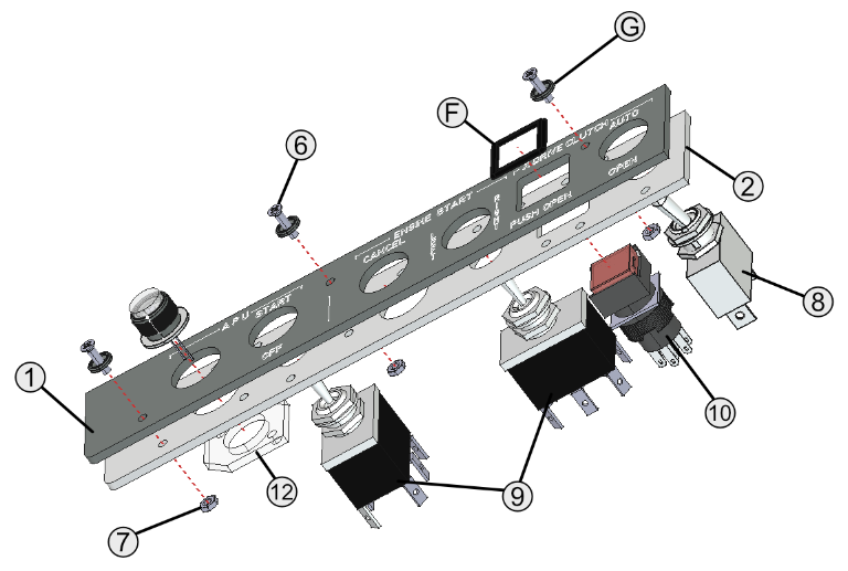
| 13 | Remove film from the middle layer and attach to the top panel with the facia grommets and 3 M3x12mm countersunk cross cut screws. |
| 14 | Attach the two momentary toggle on/OFF/on DT-DP switches to the START/OFF and LEFT/RIGHT positions, note the orientation. The START/OFF switch goes vertically while the LEFT/RIGHT switch goes horizontally. |
| 14 | Attach the toggle ON/OFF ST-SP switch to the AUTO/OPEN position with the grove facing downwards. |
| 16 | 3D print the 16mm Square momentary push button switch facia bevel and paint it black. |
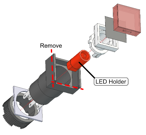
| 17 | Remove the lens from the 16mm press button. |
| 18 | paint the inside only of the red lens black. |
| 19 | Carefully (use low settings at first) engrave the "SHUT" wording in reverse on the back (painted) side. |
| 20 | Remove the LED holder from the switch. |
| 21 | De-solder the LED and attached resistor from the LED holder, this may partially destroy the holder but as long as the bottom section is intact it should all still work. |
| 22 | Solder a red 3mm 3v LED to the contacts in the LED holder. |
| 23 | Re-assemble the 16mm push button. |
| 24 | Attach the 16mm square push button to the facia. You may need to grind some of the left/right edges if it protrudes too much. The button should be level with the bezel. |
| 25 | Assemble the Type B indicator with a clear 3mm LED. |
| 26 | Attach the Type B indicator to the left of the APU section. |
| 27 | Wire switches and LEDs. |
| 28 | Cut 3 20mm lengths of 7mm steel tube and paint grey. |
| 29 | 3D print 3 7mm switch caps and paint grey. |
| 30 | Glue the 3 7x20mm steel tubes to the switch arms with hot glue. |
| 31 | Glue a switch cap to the end of each of the 7x20mm steel tubes. |
Note all .SVG files are 96dpi.
| Part | Description | File | Type |
| A | DZUS Cap | DZUSCap.stl | 3D print |
| B | DZUS Grommets | DZUSGrommet.stl | 3D print |
| C | Type B Indicator Base | TypeBIndicatorBase.stl | 3D print |
| D | Type B Indicator LED Tray | TypeBIndicatorLEDTray.stl | 3D print |
| E | Type B Indicator Body | TypeBIndicatorBody.stl | 3D print |
| F | 16mm Push Button Facia Bevel | EngineStartPanelBezel.stl | 3D print |
| G | Facia Grommet (x3) | FaciaGrommet.stl | 3D print |
| H | 7mm switch caps (x3) | 7mmSwitchCap.stl | 3D print |
| 1 | Top Layer | EngineStartPanel_TopLayer.svg | Laser cut and engraved |
| 2 | Middle Layer | EngineStartPanel_MiddleLayer.svg | Laser cut |
| 3 | Indicator Type B Diffuser | TypeBIndicatorDiffuser.svg | Laser cut |
| 4 | Indicator Type B Lens | EngineStartPanel_RunIndicatorLens.svg | Laser cut |
| 5 | Clear 3mm LED | ||
| 6 | M3x12mm countersunk cross cut screws (x3) | ||
| 7 | M3 nuts (x3) | ||
| 8 | Switch toggle ON/OFF ST-SP | ||
| 9 | Switch momentary toggle on/OFF/on DT-DP | ||
| 10 | 16mm Square momentary push button switch with Red LED 220V | ||
| 11 (Not shown) | Red 3mm LED | ||
| 12 | Run Indicator Backing | EngineStartPanel_RunIndBack.svg | Laser cut |
| 13 | 7mm Steel Tube |
I named the indicator as Type B as I had thought that the SPILS Panel BITE switch was a standard size and was going to be called Type A. After looking at several panels that have BITE switches they all appear to be different.