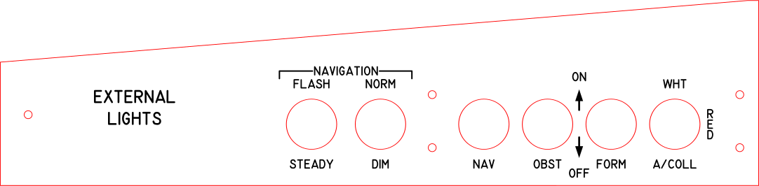
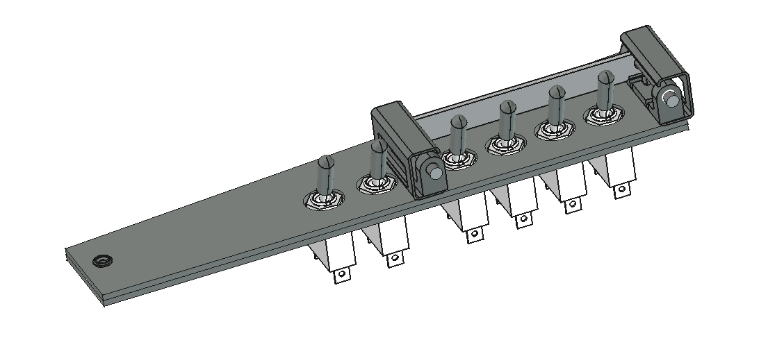
The External Lighting Panel is one of the easier to make. It's basically six simple on-off toggle switches. The gangbar assembly is slightly more involved.

 |
|
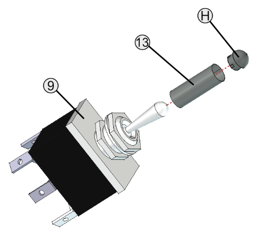
| 20x7mm switch extension |
There is a light source to this panel so it has to be made of the specified 3 mm acrylic if the back lighting is required.
1. 3D print the five parts (C, D, E, F and G) that make up the BITE switch.
2. Paint parts F and G black.
3. Using a small paint brush paint the LED bays of part F silver.
4. Press fit the cherry keyboard switch in the bottom ...
5. Place the spring over the plunger.
6. Insert the plunger into the cross shaped projection from the keyboard switch.
7. Insert the LED insert into the outer part.
8. Press the top assembly into the bottom assembly.
9. Laser cut the bottom 2 layer in a laser cutter using clear 3 mm acrylic sheet.
10. By hand use a medium drill bit to make the 2 M3 screws holes either side of the BITE switch opening chamfered.
11. Laser cut the bottom layer in a laser cutter using white 3 mm acrylic sheet.
12. Laser cut the middle layer in a laser cutter using white 3 mm acrylic sheet.
13. Laser cut the top layer in a laser cutter using white 3 mm acrylic sheet.
14. Paint the top layer grey.
15. leave the protective film on the top and bottom of the middle layer and paint the edges grey.
16. Remove the file from the top and botton of the middle layer.
17. Engrave the two vertical marks through the paint on the middle layer.
18. Engrave the text through the paint on the top layer.
19. 3D Print 2 DZUS caps and 2 DZUS grommets.
20. Paint DZUS Caps grey.
21. Attach the switch to the bottom 2 layer with the slot towards the bottom of the panel.
22. Place the four layers together and secure with 2 M3x12 mm screws through the three holes.
23. Place the bottom, middle and top layers together and secure with 2 M3x40 mm screws through the DZUS grommits.
24. Press DZUS caps over the DZUS grommets.
25. Connect the cable to each side of the ON/OFF switch.
26. 3D print the five parts that makeup the BITE switch.
27. Place a white LED in the top and an amber LED in the bottom of BITE switch openings and connect wires to the LEDs.
28. Laser cut a 1 mm thick white diffuser for the top of the switch.
29. Laser cut a 1 mm thick clear legend for the switch.
20. Laser engrave the lettering into the clear legend and use black paint to fill the letters in.
31. Attach diffuser then the clear legend to the BITE switch.
32. Attach BITE switch to the bottom 2 layer with two M3 countersunk screws.

Note all .SVG files are 96dpi.
| Part | Description | File | Type |
| C | Gangbar | ExternalLightingPanel_GangBar.stl | 3D print |
| 1 | Top Layer | ExternalLightingPanel_TopLayer.svg | Laser cut and engraved |
| 2 | Bottom Layer | ExternalLightingPanel_TopLayer.svg | Laser cut and engraved |
| F | Left Guard | ExternalLightingPanel_GuardLeft.stl | 3D Print |
| G | Right Guard | ExternalLightingPanel_GuardRight.stl | 3D Print |
| H | Left and Right Rod Guides (x2) | ExternalLightingPanel_RodGuide.stl | 3D Print |
| 7 | Steel Rod 6.5x80mm (x2) Cut two 80mm lengths from a 6.5mm Steel rod. |
Laser cut | |
| 5 | M3 flat washer (x17) | ||
| 6 | M3x16mm pan headed cross-cut screws (x3) | ||
| 7 | Switch toggle ON/OFF ST-SP | ||
| 8 | M3x40mm pan headed cross-cut screws (x2) | ||
| 9 | Switch, momentary, Cherry keyboard | ||
| 10 | Spring, Compression, 0.8mm dia wire, 14mm dia, 15mm length. | ||
| 11 | Amber 3mm 3v LED | ||
| 12 | White 3mm 3v LED | ||
| 13 | M3x25mm countersunk screws (x2) | ||
| 14 (not shown) | M3 nut (x7) |