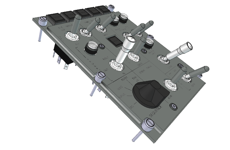
This is currently unfinished. It has taken two weeks to get this far so might be another week to finish.
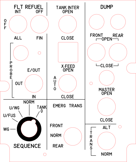
The Fuel Control Panel is a busy panel and there are lots of switches and 3D printed items that make up this panel.
My version is still lacking a couple of bits.
I think this may actually be a GR.4 panel. I've never seen the panel style that the flight manuals show for sale, this one isn't significantly different. I'm also having some issues importing the engraving layer into FreeCad 1.1.3, it's so complicated that it hangs for about twenty minutes and is unusable. Importing as an image is faster and works but the text is blurred and the wrong colour.
 |
 |
| Type B Indicator | Type C Indicator |
 |
 |
| 20x7mm switch extension | Fake locking switch cap |
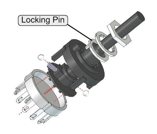 |
The 12 way rotary switch (17) needs restricting to five ways. You don't need to take it to pieces to do this, the
reason I can show the diagram on the left is because I did. It hard to locate the bits and put it all back together again. |
| 12 way rotary selection switch |
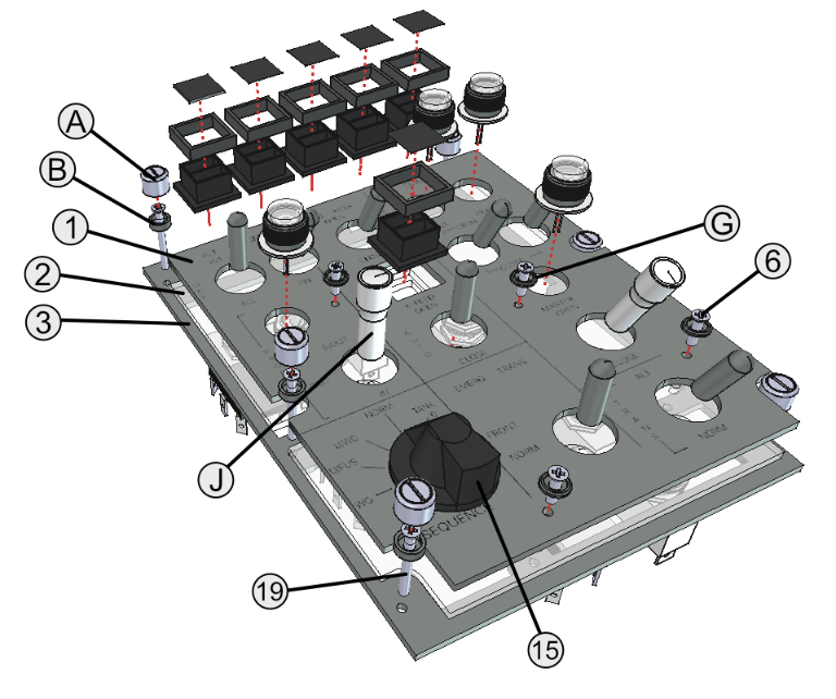
The top and middle layers are 3mm opaque white acrylic. The run indicator lens is a yellow transparent 3mm acrylic and the lens 3mm clear acrylic.
| 1 | Laser cut the top layer (1) in a laser cutter using 3 mm white opaque acrylic sheet. |
| 2 | Laser cut the middle layer (2) in a laser cutter using 3 mm clear acrylic sheet. |
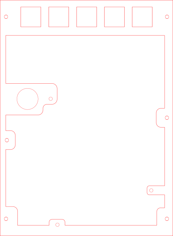
| 3 | Laser cut the bottom layer (14) in a laser cutter using 3 mm white opaque acrylic sheet. |
| 4 | Laser cut the bottom layer Pt2 (12) in a laser cutter using 3 mm clear acrylic sheet. |
| 5 | Laser cut the bottom layer Pt3 (18) in a laser cutter using 3 mm clear acrylic sheet. |
| 6 | Paint the top and bottom layers grey |
| 7 | Engrave the text on the top and bottom layers |
| 8 | 3D print 4 Facia Grommets (G) and paint grey. |
| 9 | Screw the three layers together via 4 Facia Grommets. |
| 10 | 3D print the 6 DZUS Grommets (B). |
| 11 | 3D print the 6 DZUS Caps (A) and paint grey. |
| 12 | screw the 6 DZUS caps through the DZUS grommets to the bottom layer (14). |
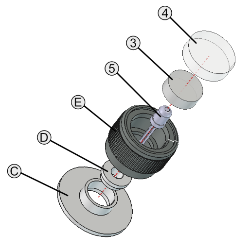
| 13 | 3D Print 4 Type B Indicators and paint grey. |
| 14 | Laser cut the Type B indicator 4 diffusers from 3mm transparent amber acrylic sheet. |
| 15 | Laser cut the Type B indicator 4 lenses from 3mm clear acrylic sheet. |
| 16 | Engrave the "OPEN" text in reverse on the back of 3 the Type B indicator lenses. |
| 17 | Engrave the "U/L" text in reverse on the back of one the Type B indicator lenses. |
| 18 | Fill the "OPEN" and "U/L" text in with black paint and clean excess off. |
| 19 | Assemble the four Type B indicators as in the diagram above. Use amber LEDs. |
| 20 | Glue the four Type B indicators into the correct locations |
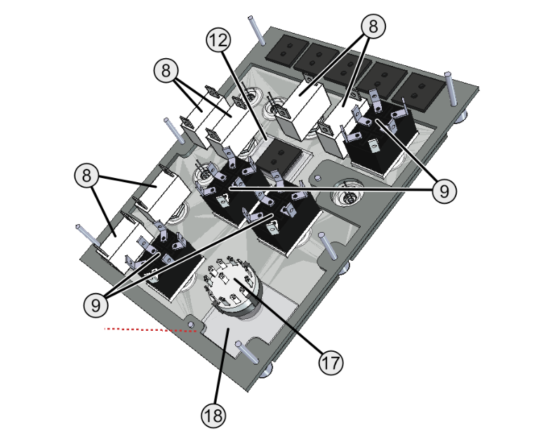
| 21 | Using the diagram above limit the rotary selection switch to five positions |
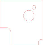
| 22 | Glue the Bottom Layer Part 3 (18) inplace |
| 23 | 3D print the Fuel Panel Rotary Knob (15) and paint black with a white line. |
| 24 | Fasten rotary selection switch in place. |
| 25 | Trim barrel lenth of rotary selection switch so that the knob (15) fits. |
| 26 | Connet the knob (15) to the rotary selection switch barrel. |
| 27 | Attach the 6 On/Off toggle switches (8) |
| 28 | Attach the 4 On/Off/On toggle switches (9) |
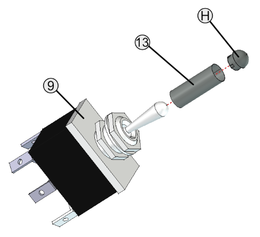
| 29 | Cut 8 20mm lengths of 7mm steel tube (13) and paint grey. |
| 30 | 3D print 8 7mm switch caps (H) and paint grey. |
| 31 | Attach the 8 7mm switch caps (H) and tubes (13) to the 8 switches shown above. |
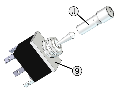
| 32 | 3D print 2 fake locking switch caps (J) and paint Silver/Grey. |
| 33 | Glue the 2 fake locking switch caps (J) to the switches shown above. |
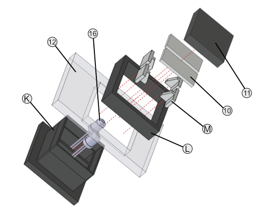
| 34 | Laser cut the 12 Type C diffusers (10) from opaque 1mm acrylic sheet. |
| 35 | Laser cut the 6 Type C lenses (11) from opaque dark green 3mm acrylic sheet. |
| 36 | Paint the back of the 6 Type C lenses (11) black. |
| 37 | Laser engrave the reversed text into the back (painted side) of the 6 Type C lenses (11). |
| 38 | Construct the 6 Type C indicators as shown above. |
| 39 | Paint the 6 Type C indicators black. |
| 40 | Laser cut the Bottom Layer Part 2 (12) in 3mm clear acrylic. |
| 41 | Glue the Bottom Layer Part 2 (12) in place. |
| 42 | Attach the 6 Type C Indicators. |
Note all .SVG files are 96dpi.
| Part | Description | File | Type |
| A | DZUS Cap | DZUSCap.stl | 3D print |
| B | DZUS Grommets | DZUSGrommet.stl | 3D print |
| C | Type B Indicator Base (x4) | TypeBIndicatorBase.stl | 3D print |
| D | Type B Indicator LED Tray (x4) | TypeBIndicatorLEDTray.stl | 3D print |
| E | Type B Indicator Body (x4) | TypeBIndicatorBody.stl | 3D print |
| G | Facia Grommet (x4) | FaciaGrommet.stl | 3D print |
| H | 7mm switch caps (x8) | 7mmSwitchCap.stl | 3D print |
| J | Fake Locking switch cap (x2) | LockingSwitchExtension.stl | 3D print |
| K | Type C Indicator Body (x6) | TypeCIndicatorBody.stl | 3D print |
| L | Type C Indicator Shroud (x6) | TypeCIndicatorShroud.stl | 3D print |
| M | Type C Indicator Diffuser Standoff (x36) | TypeCIndicatorDiffuserStandoff.stl | 3D print |
| 1 | Top Layer | FuelControlPanel_TopLayer.svg | Laser cut and engraved |
| 2 | Middle Layer | FuelControlPanel_MiddleLayer.svg | Laser cut |
| 3 | Indicator Type B Diffuser (x4) | TypeBIndicatorDiffuser.svg | Laser cut |
| 4 | Indicator Type B Lens (x4) U/L Indicator Open Indicator (x3) |
FuelControlPanel_ULIndicatorLens.svg FuelControlPanel_OpenIndicatorLens.svg |
Laser cut |
| 5 | Clear 3mm LED (x4) | ||
| 6 | M3x12mm countersunk cross cut screws (x4) | ||
| 7 | M3 nuts (x10) | ||
| 8 | Switch toggle ON/OFF ST-SP | ||
| 9 | Switch momentary toggle on/OFF/on DT-DP | ||
| 10 | Indicator Type C Diffuser (contains 12) | FuelControlPanel_TypeCDiffusers.svg | Laser cut |
| 11 | Indicator Type C Lens (contains 6) | FuelControlPanel_TypeCLenses.svg | Laser cut |
| 12 | Bottom Layer Part 2 | FuelControlPanel_BottomLayerPt2.svg | Laser cut |
| 13 | 20x7mm Steel Tube (x8) | ||
| 14 | Bottom Layer | FuelControlPanel_BottomLayer.svg | Laser cut |
| 15 | Fuel Panel Rotary Knob | FuelPanelRotaryKnob.stl | 3D Print |
| 16 | Green 3mm LED (x12) | ||
| 17 | 12-way Rotary Selection Switch | ||
| 18 | Bottom Layer Part 3 | FuelControlPanel_BottomLayerPt3.svg | Laser cut |
| 19 | M3x40mm pan headed cross-cut screws (x6) |
| 1 | The cover over the EMRG TRANS switch hasn't been made yet. The 3D file is here: FuelControlPanel_SwitchShroud.stl |